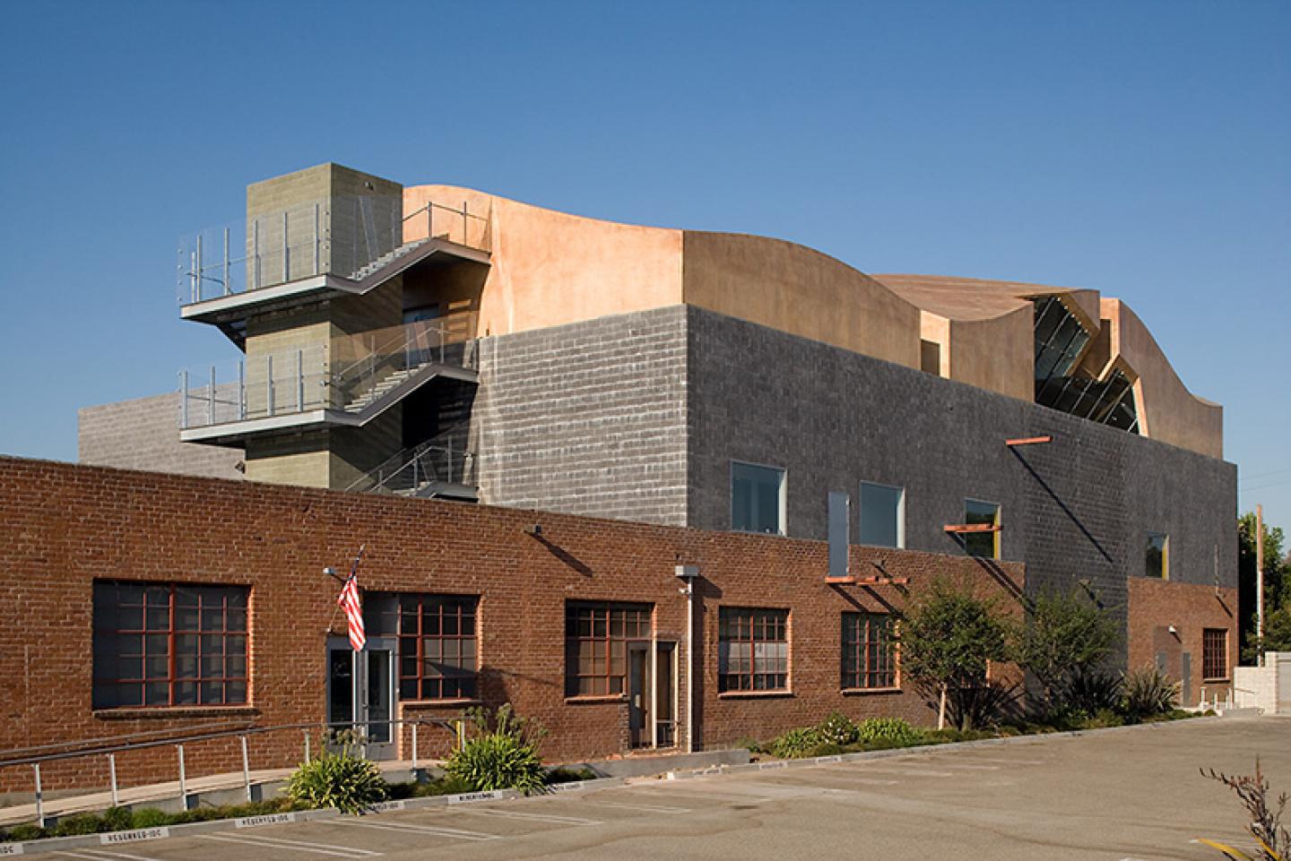
The Tennis Channel project is the most recent addition to the ongoing redevelopment of the Hayden Tract in Culver City, California, and the adjoining portion of central Los Angeles. The area of once dilapidated industrial and manufacturing buildings, is now a thriving community of new media businesses, graphic designers, and film makers.
The original, one story brick warehouse, built early 1950’s, is located just east of the now abandoned Southern Pacific Railroad right-of-way which serviced the building directly. A two story masonry box at the west end of the building was added in the late 1990’s, replacing a portion of the original brick structure, which is used as office space. The double floor height addition to the original building is a new sound stage and studio for use by film production companies in the area. The recently completed third floor addition is placed on top of the sound studio, providing space for additional offices for a Los Angeles entertainment and sports cable television station.
In order to support the third floor addition, a new perimeter of steel beams, supported on the steel and concrete block structure of the sound studio, was built on the existing studio roof. The structural design of the walls, roof, and foundations of the studio addition anticipated a future decision to expand to a third level. Steel columns are added to the new perimeter steel frame on the existing roof of the sound studio to support the new, undulating roof of the third floor. The roof shape is determined by averaging the city mandated height limit, so that the portion of the roof that extends over that limit is offset by an equal area of roof below the limit.
The roof geometry is constructed with 42 foot long, glue-laminated wood beams, located at 12 foot centers, spanning in the north south direction, and 2 inch by 8 inch wood rafters, placed at 16 inch centers, spanning from beam to beam. Each glu-laminated wood beam was milled to a unique curvature, and has a continuously changing, beveled edge on the top surface to accommodate the varying slope of the roof over the beam’s span. The CNC-milled rafters were installed perpendicular to the east or west faces of the glu-lam beams, and rotated, perpendicular to the curving roof surface. Each rafter has a curve cut on the roof-joining edge, is notched on either end for hanging off the beams, and has a milled index code for identifying its position so it can be placed within the overall roof structure.
Because the entire wood structure – beams rafters, and plywood – is exposed on the 3rd floor interior, the roofing construction must insulate the roof. The roof is composed of a plywood shear diaphragm, with rigid insulation next, then fire resistant cement board sheathing on top. The finished surface, applied over the cement board, is a translucent, on-site, spray-applied fiberglass material, developed specifically for this project, to waterproof the entire external surface of the building, and conform seamlessly to its unique curvature. The spray-on, site-applied fiberglass is used in this project for the first time.
Extensive research and testing was necessary to develop the appropriate balance of resin, color, texture, substrate, and material strength in the fiberglass. Several 12 foot by 12 foot test panels were constructed on site to evaluate the on-site spray application of the fiberglass, to study the application techniques for corner and edge conditions on walls and roofs, and to secure expansion and contraction data, insuring that the fiberglass system would perform well, as the weather and local temperatures varied over time. Half-round ridge-bumps, analogue topographic lines, were placed horizontally along the sloping roof, to slow and re-direct the flow of water off the roof.
The third floor addition is sub-divided into three interior working spaces by two intervening, 42’ long, mullion-less structural glass sky lights, which spa
2005
2007


.jpg)
.jpg)

.jpg)

.jpg)


